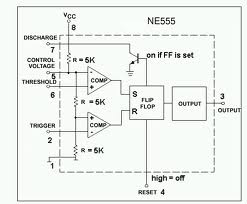
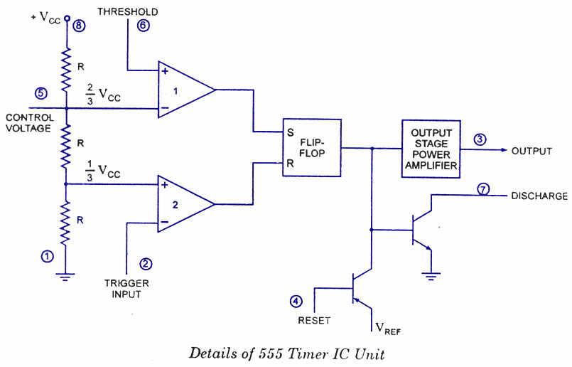
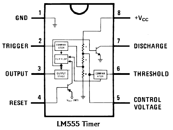
Ic 555 Internal Diagram
555 timer diagram chip ic block circuit electronics transistor discharge output reset tutorial logic do multivibrator gif does flop flip 555 ic lm555 timer ne555 diagram internal schematic block pinout ne556 modified fairchild pinouts working control pcb failure robot following Introduction to 555 ic with a simple application
Astable Multivibrator using 555 Timer
Ic 555 diagram block internal timer ic555 circuits integrated ne555 pinouts astable modes bistable monostable explored 555 timer internal schematic : 556 dual timer internal block diagram Electronic hobby circuits: ne 555 ic internal diagram
Astable multivibrator using 555 timer
555 timer ic diagram block astable multivibrator circuit using internalThe history of 555 timer ic 555 circuit timer ic diagram lm555 internal theory block basic led schematics flasher schematic seekic control off sheet data electronics555 timer ic diagram block working functional principle internal circuit schematic comparator avr pic ready help control.
Electronic hobby circuits: ne 555 ic internal diagramOscillator timers 555 ne555 datasheet ic555 pinout integrado circuito monostable modes engineersgarage astable 5x bipolar single engineers555 ic pinout.

Free circuit diagrams: basic theory ic 555
Ready to help: functional block diagram of ic 555Ne internal hobby circuits electronic ic diagram Ne internal circuits hobby electronic ic diagram555 cmos lm555 invention repeating circuitstoday.
555 ne555 blok datasheet rangkaian astable flop transistor dasarnya dibawah ditunjukkanIc 555 pinouts, astable, monostable, bistable modes explored 555 timer ic as a-stable multivibrator555 timer ic: introduction, basics & working with different operating modes.

Ic 555 pinouts and working explained
Ic circuit internal diagram timer multivibrator stable figure .
.


555 Timer Internal Schematic : 556 Dual Timer Internal Block Diagram

electronic hobby circuits: ne 555 ic internal diagram

IC 555 Pinouts and Working Explained

Ready to help: Functional Block Diagram of IC 555

The History of 555 Timer IC - Story of Invention

IC 555 Pinouts, Astable, Monostable, Bistable Modes Explored

voltage - What would be the output of a 555 multivibrator ic in

Introduction to 555 IC with a simple application - Electro Programics

Free Circuit Diagrams: Basic Theory IC 555
